SECTION SEVEN
BUILDING YOUR OWN PLATE CHOKE USING A MICROWAVE OVEN TRANSFORMER!
Finding a choke that would be of high enough inductance, be able to withstand a high potential and handle the required current, yet fit into a small place, turned out to be a nearly impossible task…at least until I began examining the standard microwave oven transformer. There are literally millions of them out there, and when plucked from a “dead” microwave oven, could be had free! Perfect!
The AC output of a standard microwave oven is about 2100 volts from terminal to case ground (the “cold” end of the primary is usually connected to the core of the transformer with a lug and pop rivet). The current ratings appear to be around the 750mA range as well.
In order to use the microwave oven transformer as a smoothing choke, the center tap of the plate transformer would be connected to the “hot” terminal of the microwave oven transformer and the case would be grounded. But before any of this could happen, the microwave oven transformer would need to be “converted” or “modified” from a transformer to a choke and set-up to have the proper inductance desired. Below is detailed information on this subject.
CONVERTING A MICROWAVE OVEN TRANSFORMER TO A CHOKE
MEASURING THE INDUCTANCE
Using a CDE942 series capacitor rated at 1.0uf / 2kv (or any reasonable capacitor of known value) in series with a microwave oven transformer and a 1000 ohm resistor, this series LCR circuit was connected to an audio generator capable of about 20 volts P-P output. Measuring across the resistor with an oscilloscope one would vary the frequency until a peak voltage would appear on the scope. Now you have two known values: the value of the test capacitor and the frequency. By use of the simple formula where (L=C) at resonance, one can determine the value of L quite readily.
I
have found that most microwave oven transformers are somewhere around
the 33 to 35 Henry range. The microwave oven transformer would need to
be modified if it were to be used as a choke as 30+ henries is too much
inductance for practical use. A value of 6 to 12 henries is more
realistic.
MODIFYING THE MICROWAVE OVEN TRANSFORMER
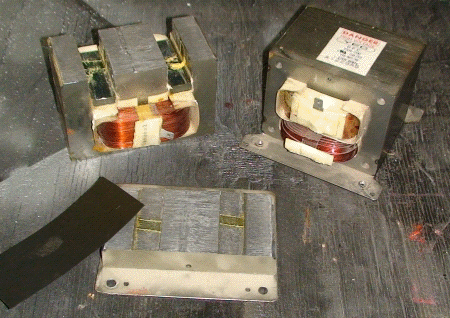
If you examine a microwave oven transformer, you will probably notice that most are manufactured with an “E / I” type of lamination construction and the “E” is welded to the “I”. (FIGURE 1). What I did was grind just enough of the weld away on both sides so I could split the two laminations apart (FIGURE 2). FIGURE 3 shows how much material ideally should be removed to split the two halves apart; just enough to split the core. FIGURE 4 shows the split core. Note the “magnetic shunts” located just above the winding. These are designed so as the microwave oven transformer becomes “overloaded”, the current does not exceed rated value under normal conditions. With the shunts still in place, I measured about 6 Henries on my test choke; so I left them intact. They may be removed if less inductance is desired.
Also note the primary (120 volt) winding and the magnetron filament winding was carefully chiseled and removed as they would not be needed. Be careful when you do this as to not damage the fine secondary winding.
Now take a beer coaster, or other suitable
“stiff” type of insulating material, and place it between the “E” and
the “I’ laminations (FIGURE 5) and put some pressure on the two halves (FIGURE 6)
Once this is done, the inductance may be measured and pressure
readjusted until the inductance is where you want it. The inductance
will change depending on how much insulation is used between the two
halves and somewhat how much pressure is placed between them. As a rule
of thumb: the more insulation, the less the inductance. More than 1/16
of an inch of insulation is not recommended. Pressure placed on the
gapped sections will also aid in reducing an audible “buzz”, which bay
occur if the laminations are left “loose”. Beer coasters seem to have a
good consistency by maintaining decent “tightness”.
Refer to FIGURE 7. Once the correct inductance is acquired, the two halves may be sewn back together by either using a MIG (wire-feed) welder, or, if that is not available, by simply squeezing together using long bolts. I do not recommend using a TIG welder, as this seems to just “blow-away” the thin lamination core material. The residual material is then ground to a smooth finish as in FIGURE 8. The finished transformer choke is shown in FIGURE 9.
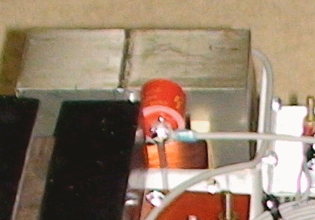
On FIGURE 10, I carefully drilled out the pop rivet and lifted the winding’s “cold” end lug and used a small door knob capacitor as an insulating binding post. This isolates the winding from case ground which allows the cold end to be connected to the plate over-current relay circuit. If you don’t do this, the over-current circuit won’t work.
Before welding the two halves together, the inductance was measured 11.7 henries. The inductance increased to 13.0 henries afterwards; a little bit high but still within reason for my application. You may wish to account for this change by going maybe 10 percent low on the inductance measurement before welding the core back together.
Another useful application of a “converted microwave oven transformer” may be as a high inductance screen supply choke. This would make for great sounding AM audio and has the advantage of greatly reduced heating that would normally occur by using current limiting resistors of a comparable value. This is due to the audio signal being converted to a magnetic field then back into useful energy and, unlike a large screen dropping resistor, there is no heat; something to think about.
FIGURE 1
TYPICAL E-I CORE CONSTRUCTION

FIGURE 2
GRINDING THE TWO CORE HALVES APART
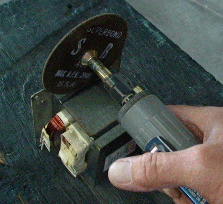
FIGURE 3
AMOUNT OF MATERIAL REMOVED
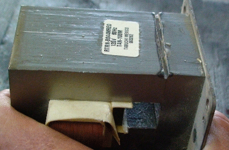
FIGURE 4
SPLIT CORE
NOTE
PRIMARY AND FILAMENT WINDING REMOVED AND
LOCATION OF MAGNETIC SHUNTS ON EITHER SIDE OF GAP
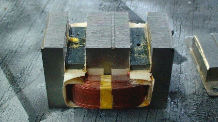
FIGURE 5
PLACEMENT OF INDUCTANCE BARRIER (BEER COASTER)
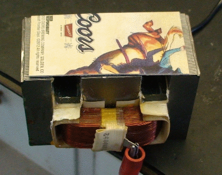
FIGURE 6
COMPRESSING THE BEER COASTER BARRIER BETWEEN THE E AND I CORE
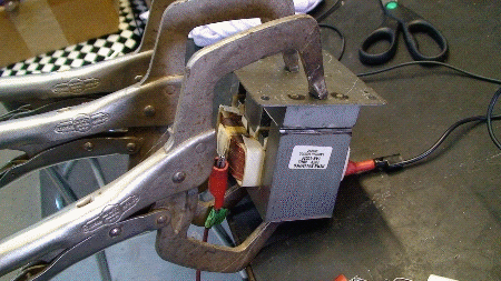
FIGURE 7
WELDING THE CORE BACK TOGETHER
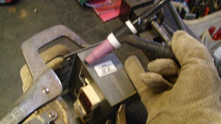
FIGURE 8
CLEANING UP THE WELD
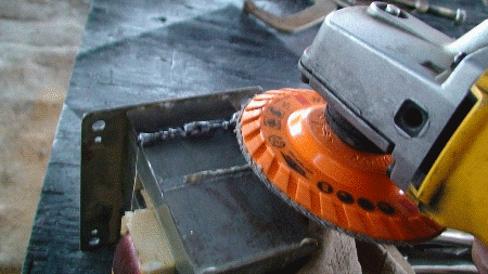
FIGURE 9
FINAL PRODUCT-12 HENRY CHOKE
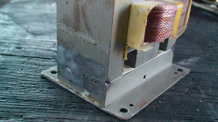
FIGURE 10
NOTE
RED DOOR KNOB CAPACITOR (STAND-OFF INSULATOR)
MOUNTED TO TRANSFORMER CORE
