SECTION THREE
POWER SUPPLIES AND PROTECTION CIRCUITS
GENERAL
For convenience of operation the 304TL modulator and 4-1000A amplifier have been designed with completely independent high and low voltage power supplies. In most transmitters of this type it is generally acceptable to operate the RF final and the modulator off of the same supply. There are several advantages in separating the power supplies:
304TL modulator fixed supply allows “set and forget” bias adjustment.
304TL modulator may be completely turned off and bypassed allowing the RF amplifier to be used as a stand-alone low level AM amplifier or SSB linear amplifier.
4-1000A RF deck’s plate voltage can be adjusted for desired output power independently from the modulator.
BRIEF DESCRIPTION OF EACH POWER SUPPLY
The 304TL modulator power has three DC power supplies and two filament supplies:
3kVDC / 0.5A choke input full wave rectified high voltage supply.
330VDC choke input low voltage plate supply for the preamp and driver amp sections.
-300VDC negative adjustable bias supply with grid-block-keyed for biasing the 304TL finals.
5VAC / 60A rated 304TL filaments transformer, inrush current protected.
6.3VAC supplies voltage to the preamp and driver tube filaments.
The 4-1000A RF Amplifier has three DC power supplies and one filament supply:
2.5 to 4kV, 700mA rated adjustable DC high voltage supply featuring inrush and fault current limiting with over-current protection.
Dual voltage screen grid power supply for low and high power operation; low power usually used for “tune-up” if uncertain of load conditions.
-200VDC negative adjustable bias supply, grid-block-keyed for 4-1000A “cut-off” when not transmitting, (i.e. receive mode).
7.5VAC / 22A inrush protected 4-1000A filament transformer.
DESIRED GOALS
It seems every person has their own preferences when it comes to building power supplies, or anything else for that matter, particularly when it comes to protection circuits, component sizes, etc. Many items may factor into the final product such as choices of “available” components, cabinet size, proposed layout, budget, and so on. That said, there probably really is no real “best” way or method so long as you do the best you can, it works and works well.
By comparison, commercial transmitters of similar power and quality of the Globe Master use very large and bulky cabinets and components. This is because unexpected commercial “down time” could get very expensive in a real hurry, and, if you can’t easily get to and work on the suspect “bad” components, you might be down for a long time.
The Globe Master was designed to be much smaller in size compared to its commercial counterpart, be relatively easy to maneuver around the shack, pack a big punch and be reasonably easy to perform maintenance on. The Globe Master has a lot of “stuff” in a small package; but only the absolute minimum “must have” items were commissioned for service (due to space constraints) No bells and whistles here, just the necessities. Only the highest quality components available to the builder at the time of construction were used. No shortcuts were taken and no quality was compromised. All circuits were thoroughly tested and carefully evaluated before moving on to the next circuit. The aforementioned practices helped ensure not only a smoother road to success, but also a reliable transmitter that would (hopefully) provide years of enjoyment to the owner.
4-1000A POWER SUPPLY
THEORY OF OPERATION
The
author has chosen to go the route of a “well filtered” design in
building the Globe Master. That doesn’t necessary mean “well
regulated”. This was going to be an AM transmitter, so, from an AC
symmetrical point of view, the total components of an AC RF signal
should always equal zero, which in turn would theoretically make the
load constant thus resulting in a relatively constant DC voltage to the
load.
It was therefore chosen to use choke input design on the DC plate
supply. Other factors in the design were the availability of
components. For instance, when just the “right size” plate transformer
was found, it was physically too big to fit into the permitted space. A
3KVA, 7200VCT secondary, 240VAC secondary transformer was readily
available and did fit the space requirement. Unfortunately the DC
output voltage would be much higher than needed; nearly 4800VDC, so it
was decided to use an input choke (a converted microwave oven
transformer was used for this purpose).
The choke was set-up to reduce the full load voltage by around 1200 volts, or 3600 B+ volts output at full load. This was accomplished by carefully tuning the input choke by using a small high voltage capacitor on the input terminal of the choke. The choke needed to be about 12 Henries or so, be able to withstand the available high voltage to ground and needed to fit into a small 4” x 4” x 5” space.
LOW VOLTAGE START-UP AND RELAY SEQUENCING
SCHEMATIC DIAGRAM

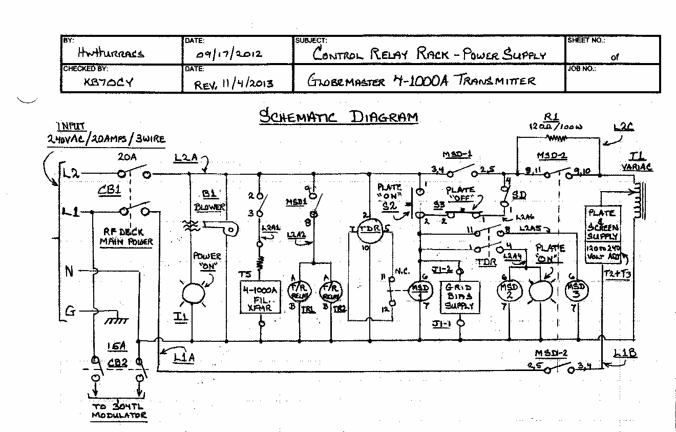
When the main AMP POWER circuit breaker CB1 is enabled, the AMPLIFIER indicator lamp, RF amplifier blower fan B1 are energized and the plate time delay relay TDR is armed. Placing the FILAMENTswitch (S1) to the ON position energizes the 4-1000A filament transformer and the negative grid bias power supply.
It was assumed that a dual primary 240 volt center tapped, 7.5 volt secondary filament transformer had been installed in the RF deck. It was discovered that a 10 volt, 22 amp filament transformer had inadvertently been installed instead. The 4-1000A requires a filament voltage of 7.5VAC to operate properly. This was actually a blessing in disguise. I found that placing a 20 ohm, 20 watt resistor in series with the filament transformer not only gave me the correct voltage, but also reduced the inrush current to the filament by just over the operating current. Heavy inrush current can greatly reduce the life of the tube, so two problems were solved with one solution. The extra heat generated by the resistor turned out to be a good trade-off.
The PLATE-ON / PLATE-OFF (S2 and S3) are of standard “start-stop” latching relay design enabling the addition of the plate over-current tripping scheme.
When the PLATE-ON pushbutton is pressed, relay MSD1 is picked up which in turn keys the parallel DOW KEY antenna relays, energizes the plate transformer “pre-charging” resistor R1, and enables time delay relay TDR. After an approximate one second time delay, the main plate power relay MSD2 and PLATE ONindicator light is energized. The plate circuit is now fully energized.
4-1000A VARIABLE OUTPUT POWER
DC PLATE AND SCREEN SUPPLY
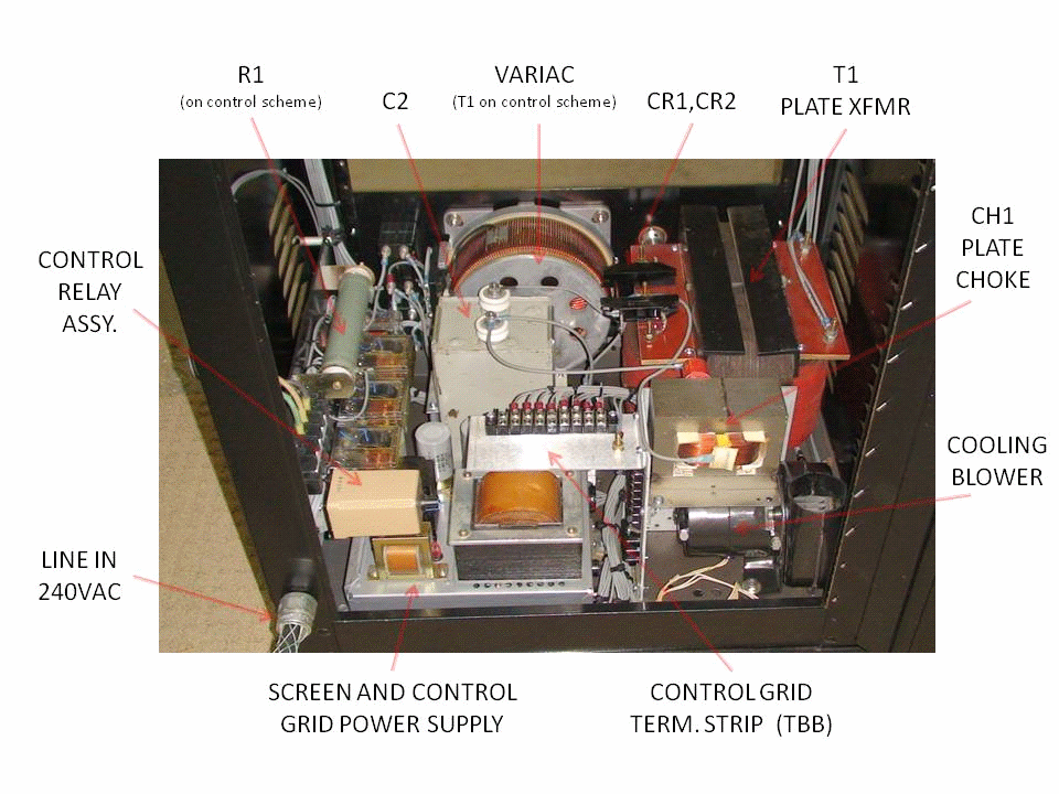
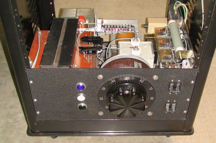
A 120 volt / 22 ampere Variac is employed for adjustment of both the PLATE and SCREEN power supplies simultaneously. The Variac is tapped from the center point of a three-wire 240 VAC service and requires a solid NEUTRAL connection for proper operation. The idea behind this particular design is that one can use a much larger current capacity Variac, which starts out on the low end at half the maximum available plate voltage and can be increased to its maximum value without the need for a physically larger 240 volt Variac to do the same job. I don’t know of anybody who starts a transmitter at “zero output power” and goes up from there. A 240 volt Variac is MUCH BIGGER AND HEAVIER than its equal current-rated 120 volt counterpart. In this application, it’s kind of like having a variable tap-changer on your plate transformer! …Low, Medium and High Power (and anything in between), at the twist of a dial. This result is that the no-load DC output voltage may be adjusted from approximately 2400 to 4800 volts allowing for quite a range of output power(s).
As mentioned earlier, the SCREEN power supply is connected in parallel with the PLATE TRANSFORMER input. Maximum input voltage to both PLATE and SCREEN transformers is 240 VAC. The secondary of the screen transformer has two taps: a 120 volt and a 480 volt tap. These two taps are brought to the front panel’s SCREEN BIAS – HI/LO switch. The amplifier is normally operated with the SCREEN BIAS switch in the HI position and delivers screen bias voltages between about 300 and 600 volts, depending on position of the POWER CONTROL VARIAC. The LO position may be used like a “TUNE” switch, as the transmitters output power is substantially reduced due to the lower voltage being delivered to the screen.
4-1000A
PLATE TRANSFORMER HIGH VOLTAGE RECTIFIERS,
FILTERING AND CURRENT LIMITING
HV SUPPLY COMPONENT REAR VIEW

HV SUPPLY COMPONENT FRONT VIEW
as a Republican
SCHEMATIC DIAGRAM
HIGH VOLTAGE PLATE SUPPLY

SCHEMATIC DIAGRAM
SCREEN GRID POWER SUPPLY

To
keep the size down, the main power transformer uses two 2 amp, 20kV
solid state rectifiers in a full wave configuration. The center tap, or
B- of the plate transformer, is fed into a home-brew “input choke”
which is series connected to ground via an over-current relay. The B+
side is fed into a 50 ohm, 20 watt wire-wound current limiting resistor
which is terminated into a 11uf, 5kV oil filled capacitor. This
current limiting resistor aids in reducing the maximum fault current
from a couple thousand amps to approximately 60 amps at 3kv plate.
Should a fault occur, severe damage is mitigated even further by use of
an over-current relay. The over-current relay is an ice cube type relay
with a 12VDC coil. The relay reliably picks up between 7.0 and 7.1
volts. To establish a 700mA pick-up, a 10 ohm, 20 watt wire wound shunt
resistor was placed in parallel across the over-current relay’s 12 VDC
coil. When the over-current relay picks up, the primary plate
start-stop circuit is interrupted and the main plate power source relay
trips.
At full load, the power supply will deliver over 3600 volts B+ @ 500mA. The input choke is a modified microwave oven transformer converted and “fine tuned” for a 1200 volt drop (at 500mA) by placing a 2uf / 2.1kV oil capacitor of the same type used in microwave ovens from the “hot” leg of the modified choke to ground. I tried various capacitor values from 1uf to 4uf and the 2uf seemed to give the results I was looking for. A detailed description of how the microwave oven transformer (MOT) was re-worked into a choke is at the end of this article.
Additional regulation is provided by two large 50k / 200 watt bleeder resistors connected in series located at the top of the transmitter. The configuration used here works well as it provides good filtering, protection and the necessary voltage drop without any unnecessary heat.
4-1000A CONTROL GRID BIAS SUPPLY
SCHEMATIC DIAGRAM

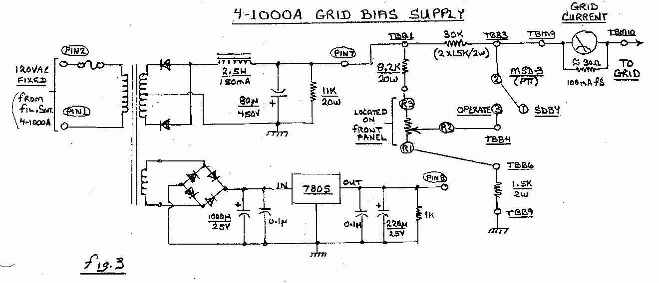
It was decided early on that the amplifier might like to be used not only for HIGH LEVEL AM operation, but perhaps be driven by a LOW LEVEL AM EXCITER or SINGLE SIDBAND TRANSMITER as well, so a switchable bias combination for these options would be needed. It was suggested that a method called GRID-BLOCK KEYING be used to accomplish this.
Initially the transmitter was keyed up by enabling the PLATE-ON push button which would key the ANTENNA RELAY and after a second or two time delay, energize the plate transformer and an auxiliary relay contact would un-block the grid of the 304TL modulator.
This design proved to be lame at best:
When you keyed up, you had to remember to also key the exciter, mute the receiver or you’d get a tremendous audio feedback, all the while your arms would flail in all directions pushing buttons, twisting knobs, etc. Without fail you inevitable got the “sequence of operation” out of order.
I decided to rewired a front panel switch for two “KEY MODE” types: PLATE MODE and PTT MODE
When in PLATE MODE and the PLATE-ON push button is depressed, the entire transmitter is keyed after a two second time delay. This is a little rough on the HV PLATE SUPPLY as the high voltage is constantly being switched on and off between transmissions. Probably a great setting if you like BROADCASTING.
When in PTT MODE, the HV supplies are always energized, so no power transformer surging occurs, rather a combination of auxiliary relay contacts are picked-up to perform the following actions:
Automatically keys the EXCITER, MODULATOR, ANTENNA RELAY, and MUTES THE RECEIVE (through either NO/NC contacts). ¼ inch mic jacks are used for the KEY EXCITER, MUTE RECEIVE and PTT TRANSMITTER functions. They are conveniently located on the rear lower left side of the transmitter.
I found the latter method of keying to be superior over the previous one.
Actual grid bias is determined by the position of the GRID BIAS CONTROL on the RF DECK CONTROL PANEL and the TYPE OF OPERATION (AM, SSB). The 4-1000A grid always has a negative voltage present when unkeyed.